
Production-Grade Highly Available Web Platform on AWS
Global DNS/CDN edge with WAF, a Multi-AZ ALB into independently scaled web and API tiers, an RDS primary with a read replica, ElastiCache, and regional Secrets Manager and AWS Backup.
Open editable diagramArchitecture diagram
Edit this exact diagram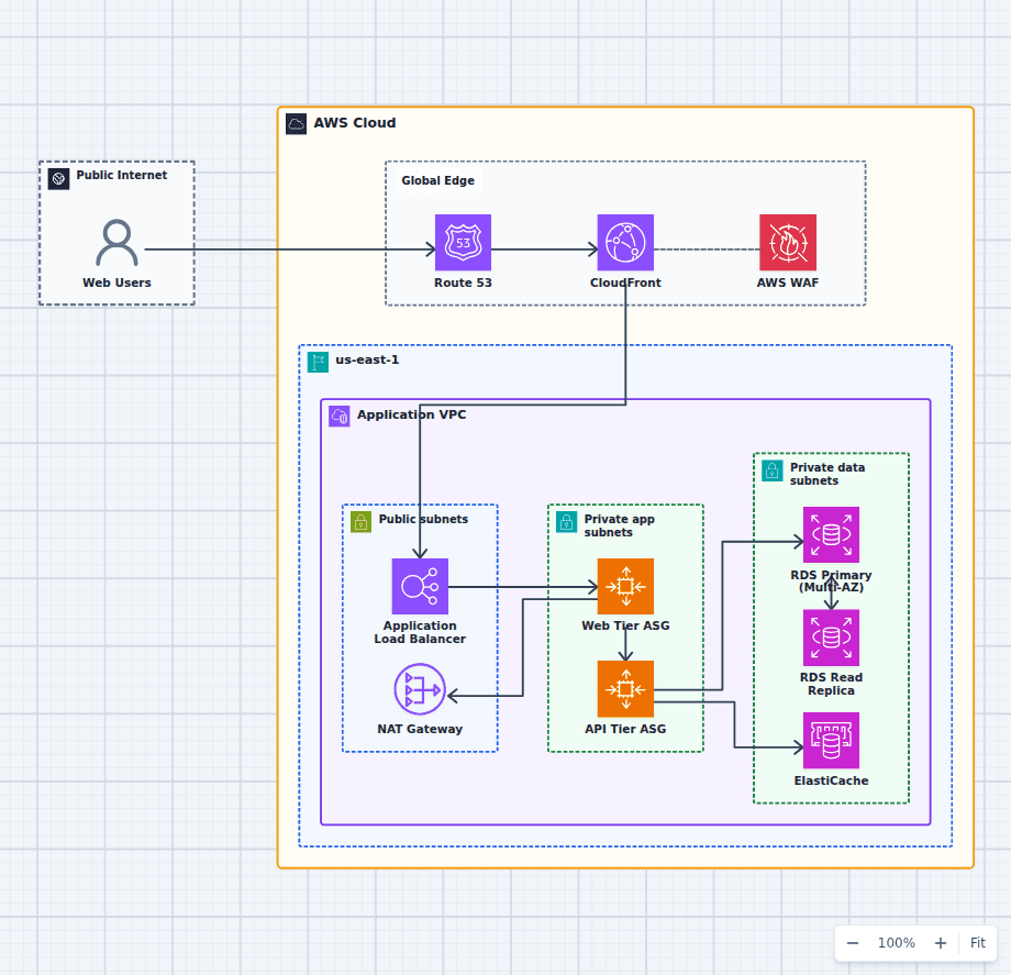 Open on the canvas
Production high availability AWS web architecture diagram with Route 53, CloudFront, WAF, ALB, Auto Scaling web and API tiers, RDS, ElastiCache, and private subnets. The image links to a fully editable BuildPlane starter.
Overview
Amazon Route 53 sends users through CloudFront and AWS WAF to an Application Load Balancer spanning multiple Availability Zones. Independently scaled web and API tiers run in private subnets and use Amazon ElastiCache and a replicated Amazon RDS database for shared state. NAT Gateways provide zone-local outbound access for private workloads.
Components
- Global Edge: Route 53 resolves the domain, CloudFront caches and terminates TLS, and WAF filters traffic before it reaches the Region.
- Load Balancing: An internet-facing ALB in public subnets health-checks targets and spreads requests across Availability Zones.
- Compute Tiers: Separate Auto Scaling Groups let the stateless web tier and the API tier scale on their own signals.
- Data Layer: An RDS Multi-AZ primary with a read replica, fronted by ElastiCache, separates durable writes from high-volume reads.
- Egress: A NAT gateway gives the private tiers controlled outbound access for patching and dependencies.
Traffic Flow
- Users resolve the domain in Route 53 and hit CloudFront, which forwards dynamic requests after WAF evaluation.
- CloudFront routes origin traffic to the ALB, which balances across the web tier in private subnets.
- The web tier calls the API tier and egresses through the NAT gateway for outbound calls.
- The API tier reads from ElastiCache and writes to the RDS primary.
- The RDS primary replicates asynchronously to the read replica for read scaling.
Customize First
- Pick instance/engine sizes, cache policy, and replica count that match your read/write ratio.
- Add a second Region with Route 53 failover and cross-Region replication when your RTO/RPO requires it.
- Add Secrets Manager for credential rotation and AWS Backup for point-in-time recovery.
Related AWS guides
Understand the decisions behind this diagram
Use these practical explanations to compare services, failure boundaries, and operating tradeoffs before adapting the architecture.
Networking
ALB vs NLB: How to Choose the Right AWS Load Balancer
ALB understands web requests. NLB moves network connections with very low overhead. The right choice follows from the protocol and routing behavior your application needs.
Read the guideArchitecture
How to Design a Highly Available Web Application on AWS
High availability is not a product switch. It comes from removing single points of failure and proving the application can keep serving when a component or zone fails.
Read the guideAWS Certification
AWS Solutions Architect Associate Study Guide for SAA-C03
SAA-C03 tests architectural judgment. Build a decision matrix, trace real diagrams, and practice explaining why three plausible answers lose to one requirement.
Read the guideDesign rationale
Decisions that shape this architecture
Use the edge to protect and cache before the Region
Route 53, CloudFront, and WAF reduce avoidable origin traffic and provide a clear public protection boundary before requests reach the ALB.
Keep private tiers independently scalable
Web and API Auto Scaling groups respond to different signals. This prevents a busy presentation layer from forcing identical capacity into business logic.
Separate cache, writes, and read scaling
ElastiCache handles hot data, the RDS primary owns durable writes, and a read replica serves suitable read workloads. Each path has different consistency and failure behavior.
Before production
Operational checks
Test cache loss, database failover, and read-replica lag under realistic load.
Set scaling policies from measured latency, saturation, and queueing signals.
Use one NAT gateway per Availability Zone when zonal independence justifies the cost.
Validate backup restore, not only backup creation.
Scope and tradeoffs
What this diagram does not solve
The design is still regional
Global DNS and CDN services do not make the origin multi-Region. Regional recovery requires another regional stack and a data replication plan.
More components create more operating responsibility
Cache policy, replica lag, scaling thresholds, NAT cost, patching, secrets, and deployment safety require ownership and observability.
Common questions
Frequently asked questions
Why put CloudFront in front of an ALB?
CloudFront can cache content, terminate connections near users, reduce origin load, and provide a global attachment point for WAF before forwarding dynamic traffic to the ALB.
What is the difference between RDS Multi-AZ and a read replica?
Multi-AZ provides a synchronous standby for availability. A read replica is an asynchronous copy used primarily to scale eligible reads.
Does this architecture require two Auto Scaling groups?
Separate groups are valuable when web and API workloads have different releases, resource profiles, or scaling signals. A simpler product can combine them.
Keep exploring
Related AWS architectures
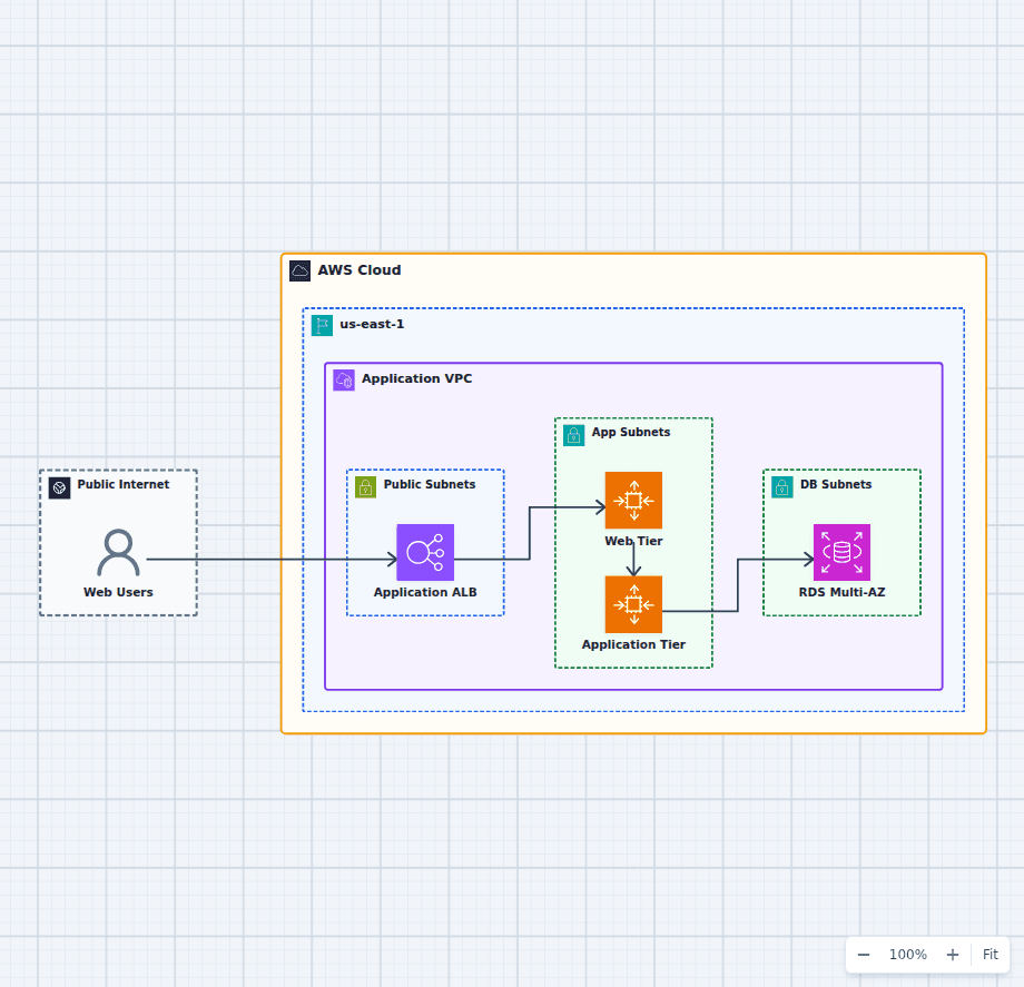
Highly Available Three-Tier Web Application on AWS
This starter architecture separates ingress, presentation, application logic, and relational data so each tier can fail and scale independently. It is a practical baseline for teams moving a conventional web application onto AWS without collapsing every responsibility into one server.
Explore the architecture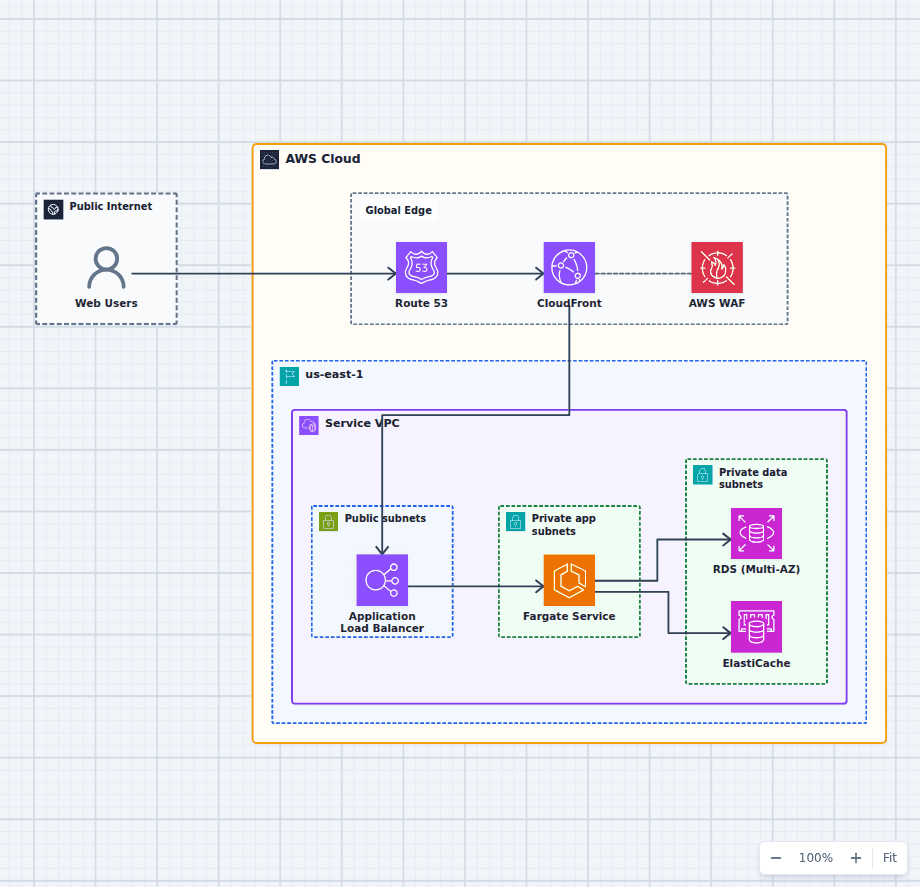
Containerized Web Service with Amazon ECS and Fargate
This architecture runs a production container service without an EC2 host fleet. A protected global edge forwards to a Multi-AZ load balancer, Fargate tasks stay private and reach data services over the VPC network, and managed image, secret, and observability services support the runtime. Every component here is one an ordinary web application needs eventually, which is why this shape is a common destination for teams outgrowing a single server and for teams who found Lambda too constraining.
Explore the architecture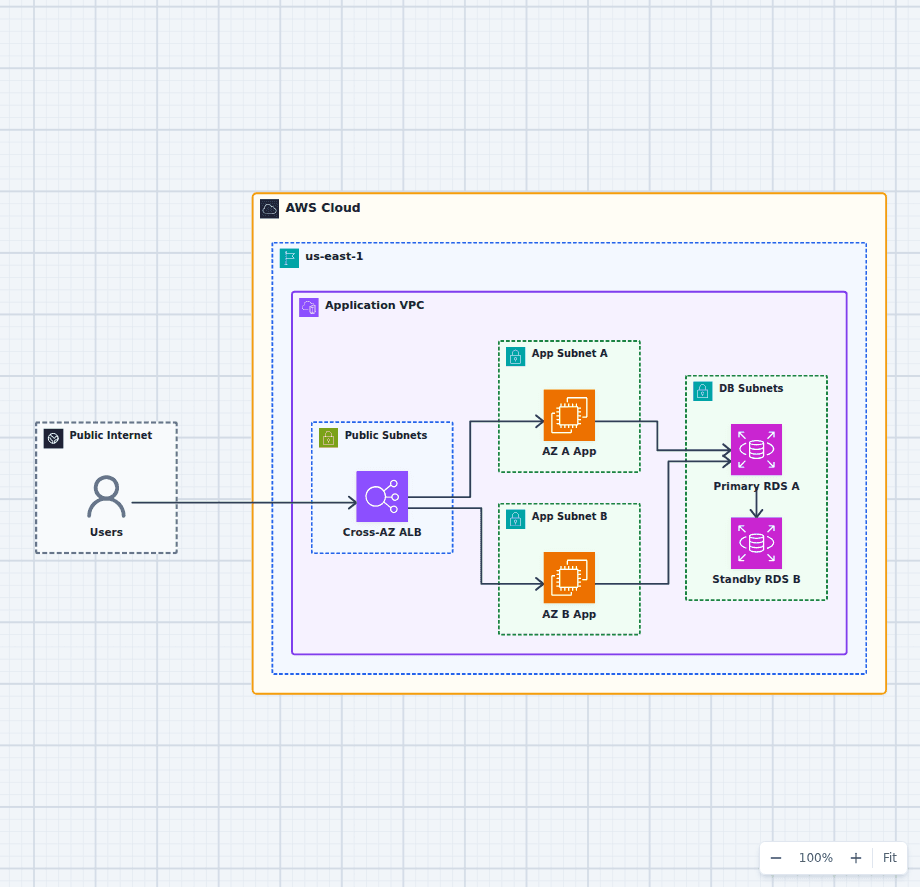
An AWS Application That Survives an Availability Zone Failure
This architecture focuses on one failure question: what happens when an entire Availability Zone becomes unavailable? Healthy application capacity remains in the other zone, the load balancer removes failed targets, and RDS can promote its synchronous standby.
Explore the architectureFrom reference to working draft
Adapt this architecture with your AWS AI Agent
Start from the exact diagram in this guide. Change requirements, challenge a decision, or ask what fails first, while keeping the architecture editable.